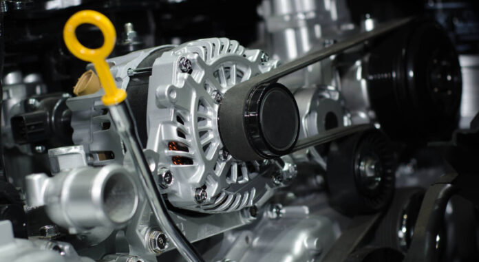
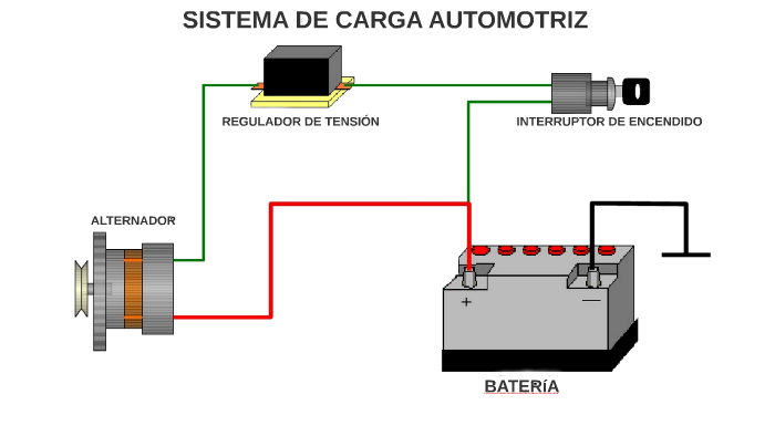
A alternator It is responsible for converting rotary energy into electrical energy, this occurs by moving a magnetic field (the armature) through the coils in the casing. The alternator is the part of your car that supplies energy, having transformed mechanical energy to get it. If you are having problems with the alternator, do not worry, here we will tell you why does your alternator only charge when accelerating.
How does an alternator work?
As we mentioned, the alternator converts rotary energy into electrical power by moving a magnetic field. In order for the alternator to generate electricity, the magnetic field must be present. It is created by the excitation current passing through the charge warning light and the parallel resistor. Note that:
- if the excitation current is too weak due to a faulty resistor, bulb, or connection, but it is present, the alternator will begin to charge only at higher RPM levels;
- Instead, if the excitation current is not present at all, then the alternator will never charge.
After the alternator begins to charge, it supplies its own field current. Since there is now voltage on both sides of the light and resistor combination, the light turns off. Once the alternator begins to charge, the light/resistor combination has no effect. If the charge warning light is on, there is voltage on one side of the bulb and not the other, and a problem occurs, usually with the alternator.
Why does my alternator only charge when I accelerate?
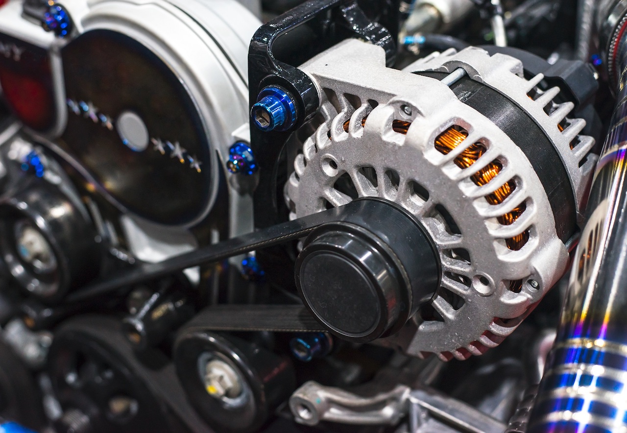
If your alternator only kicks in after accelerating (2000 RPM speeds, 3000 RPM speeds, etc.) It’s because that’s where the alternator self-activation occurs. This means that the control lines are not properly connected to the alternator, are broken, or are shorted somewhere.
The alternator coils produce AC voltage. The alternator includes six charging diodes, that is, one-way check valves for electricity, which convert AC voltage to slightly pulsating DC voltage. Yes an open diode fails, the charging amperage will be reduced. Yes a shorted diode fails, there will be an AC ripple in the output voltage and a hum will be heard on the radio. The more diodes fail, the worse the conditions.
- It may interest you: What happens if a car alternator gets wet?
Factory Workshop Manual: Charging Circuit
There are numerous wiring components in a vehicle that help to generate power for the alternator, in relation to this, and to find out what is specifically happening to your car. should check the Manufacturer’s manualsince there are several points of failure in the alternator charging circuit.
The charging circuit is usually located between pages 97-31 and 97-45 of the Factory Workshop Manual Wiring Diagrams, we will briefly explain some points so that you can identify them in the circuit:
The gray area at the top of the page is the Central Electrical Panel.
- All lines represent the wires behind the Panel. Connected wires are mirrored with points where they cross.
- Roman numerals indicate the relay positions. These are identified on the panel, but you will need a flashlight to read them.
- The relay diagrams show the terminal numbers (standardized) and the basic mechanism inside the relay.
For example, the numbers at the bottom of the gray area show the plug terminal connections. Sockets are written from left to right, starting with A on the far left. You do not have an I socket (i). The shorter plugs in the center are out of sequence: they are Y and Z. The terminals of each plug are arranged:
4 8
3 7
2 6
fifteen
Therefore, “E6” is the terminal next to the bottom on the right hand side of the fifth socket from the far left.
Meanwhile, the car’s wiring is shown with solid or broken lines. Solid lines indicate a solid color; for example, all unswitched ground wires are solid brown. All switched ground wires are dotted and indicate a brown wire with a colored stripe.
Other dotted cables are different base colors with a thin stripe of a different color. For example, the wire that supplies power to the turn signal flasher is a dashed line marked “bk/ye,” showing a black wire with a yellow stripe.
Meanwhile, the gray squares in the main field are devices in the car, such as the emergency flasher switch. The numbers around the box show the connection terminals (again, the same standardized numbers).
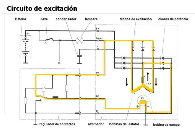
Power to excite the alternator
The power to excite the alternator has an elaborate route, it could be that your problem is the product of a failure in this route:
- Battery to ignition switch. (97-31)
- Power switch to bus 15 (general switched power bus). (97-31)
- Bus 15 to terminal H7 of the central power panel. (The connectors are AZ, from left to right at the bottom of the panel.) (97-45)
- H7 on a black wire to terminal 1R in the instrument case. (97-45)
- Terminal 1R to the light of the Generator, and to a resistor mounted in parallel to the light. If the light burns out, the alternator will not receive enough power to generate. A bad connection or bulb in the pod is a likely problem. (97-45)
- From the light/resistor to the 2R terminal on the capsule. (97-45)
- Terminal 2R via blue wire to terminal H8 of the central power panel. There are two blue wires here – power goes to the central warning computer and to H8. (97-45)
- Terminal H8 to terminal Z6. (97-31)
- External terminal Z6 via black wire to terminal Z1. (97-31)
- Terminal Z1 inside terminal O8. (97-31)
- O8 terminal on a blue wire to the alternator. (97-31)
Most common faults in the charging circuit
Numerous points of failure can be found in this circuit, although some of the most common include:
- Burnt out cargo light bulb.
- Failed parallel resistor (back of voltage meter).
- Poor connection at the 14-pin connector located in the engine compartment on the right fender, just below the jump start terminal. Be careful: this connector may fall apart while you clean it!
- Broken wire.
Some tests you can do to check this are:
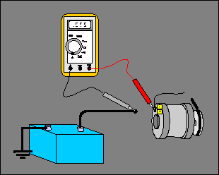
- Turn the key on so all warning lights come on, if you don’t see a red light on the charge indicator, the bulb is blown.
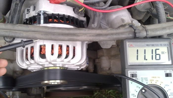
- If the light comes on then start the car and without revving the engine check the voltage at the hot post it should be above 13.5. If not, rev the engine and see if the charging system is giving this reading, if it is then there is probably a break in the charge wire going to the alternator which goes through the 14 pin connector. You should remove the blue wire from the back of the alternator and detach the 14 pin connector to see if there is continuity. If there isn’t, the cable is damaged.
Writing gossipvehiculo
